Saving my car; a project documentation
The complete bottom-end rebuild, turbocharger core replacement, and RWD conversion on a 2012 BMW 535xi F10 after catastrophic turbo FOD contamination. Performed entirely in a home garage with zero prior mechanical experience.
Chapter 1
I initially purchased this 2012 BMW 535xi from Don Valley Lexus in the spring of 2023. It saw its first winter with me the following year. To be honest, it was a bad choice of vehicle to buy, as nearly all older German luxury cars are money pits. Over that first year, it developed a couple of glaring problems that, quite frankly, the dealership had lied to me about. The front passenger door lock wasn't working, and the car had a bad alignment due to broken suspension springs likely from age and wear. The interior door pull handles had that classic BMW melting plastic issue, though the leather itself was still in excellent condition.
I immediately got to work fixing the little things to improve the experience. However, soon after that first winter, I noticed the car would experience choppy acceleration under moderate throttle. This sent me down a rabbit hole of mechanical diagnostics, checking everything from airflow control to the transmission. Eventually, I figured out that the transfer case system in these xDrive vehicles is designed with a wet clutch that constantly performs micro-slips during normal operation. Usually, this is smooth, but in an older vehicle, it can start to stutter. I realized I would likely need a new transfer case, or I could convert the car to RWD.
Coming from Japanese cars known for reliability, I already knew that a German car requires proactive and constant maintenance. It was my job to rise to the challenge or forfeit the car, so I was constantly looking for things to fix. The following summer of 2024, the car had a few more issues. The air conditioning stopped working one day; I pulled the AC coils to check for continuity and immediately noticed they were shorted. I replaced them the following week. But that wasn't the end of it!
 Image slot 1
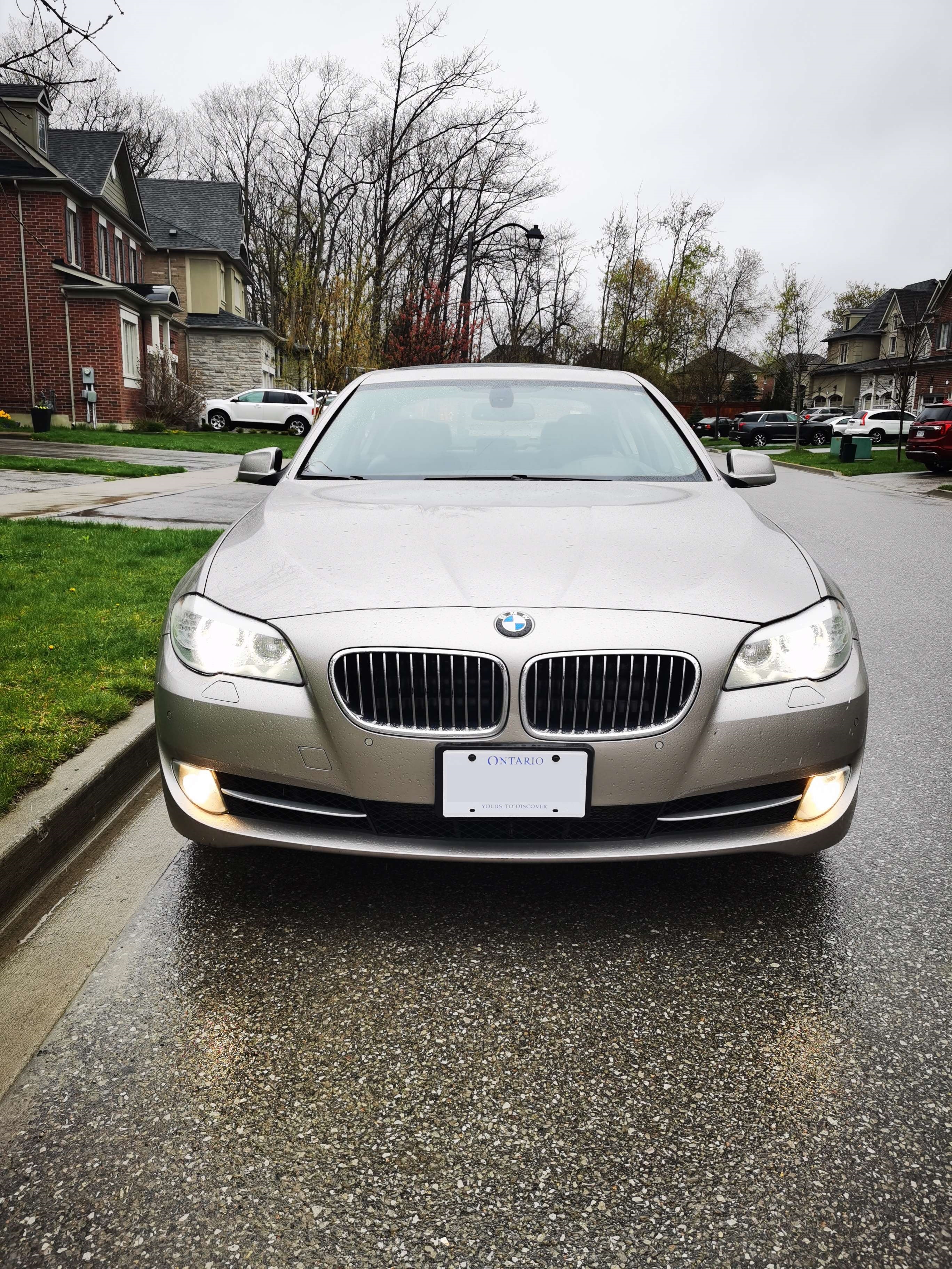 Image slot 2
Chapter 2
The final issue I kept running into was a low boost pressure plausibility error under high engine load, triggered by a check engine light and "Powertrain Malfunction" warning on the dash. At first, there were no other symptoms, just the warning. The car still accelerated fine without hesitation. Still being inexperienced, I began to suspect different parts of the engine's airflow control system. I checked for leaks but couldn't find any. I checked the turbo diverter valve, which I suspected might be faulty since they contain a rubber diaphragm that can easily crack from age and heat cycles, but it was fine. Yet the issue persisted. I had also noticed a newly occurring whining noise that corresponded with engine RPM, along with a constant low boost plausibility error code that kept flashing whenever moderate or high throttle was applied.
One summer night, I was driving back home from work when I noticed a bunch of warning lights suddenly start flashing TPMS, traction control, and ABS. The engine was low on power and wouldn't accelerate much. I suspected it wasn't possible for all of these errors to occur at the same time, or rather, it was extremely unlikely. I investigated and diagnosed the issue as voltage creep from a failing alternator, which at the time had started outputting 15V+ to the battery.
After replacing the alternator, the voltage issues disappeared. But during the alternator replacement, I ran into a complication: since the alternator sits on a bracket below the engine intake manifold, it requires removal of the manifold to access all the bolts and connectors. When I removed the manifold, I noticed something extremely concerning. There was shiny sand or metal dust speckled throughout the intake manifold.
I knew this couldn't be good, so I traced the airflow back to the charge pipe. It was full of metal debris too. I looked at the intake and filters, both were clean. So the source had to be somewhere between those two points. Eventually, I decided to scope the turbocharger with an endoscope that my dad happened to have. That's when I saw it: the compressor turbine was completely destroyed.
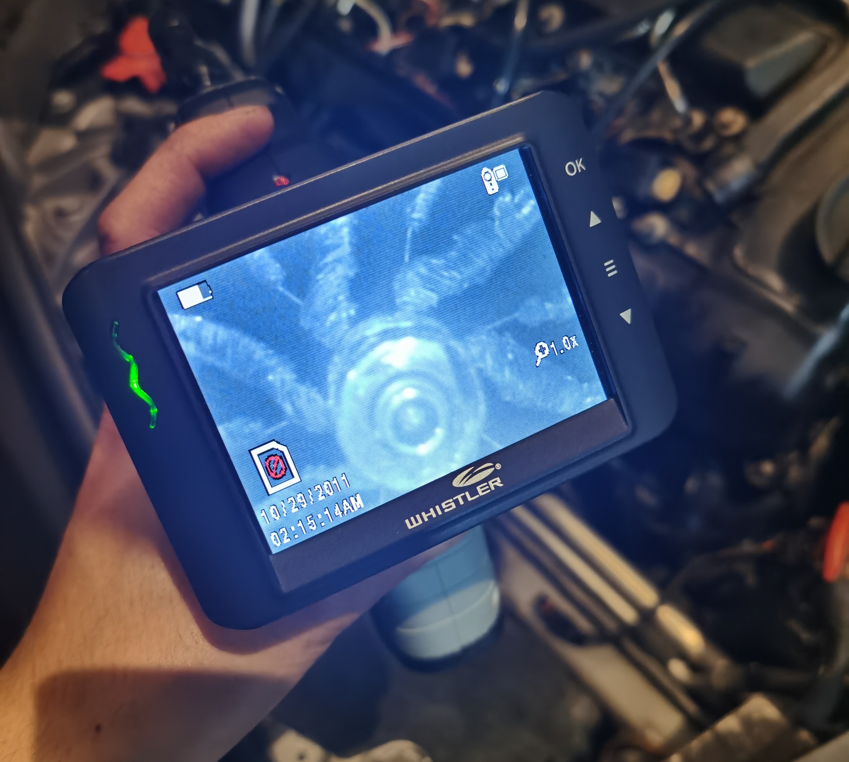 Image: Destroyed turbocharger compressor
Terrible thoughts raced through my head. If the turbine was shredding metal bits this whole time, where were they ending up? Inside the engine? In the cylinders? I checked the intake valves and did see a few specks of metal, but nothing significant. Later, I drained the oil and faced my worst nightmare: the oil was heavily contaminated with metallic chips, and the oil filter was filled with glitter. My car was about to have a catastrophic failure.
The oil was heavily contaminated with metallic chips, and the oil filter was filled with glitter. The turbo had been sending metal debris into the engine.
Chapter 3
Initially I was crushed. I thought this car would be completely totaled. Generally a turbo FOD is not recoverable without an engine replacement or significant rebuild. I looked around for mechanic quotes and was told somewhere in the range of $10,000 for diagnostics, repairs, and labour. I tried the dealership and was offered a bill of nearly $30,000! I even considered selling the car to a junkyard or used parts dealer. I had offers for around $2,000 for my car, which I had spent nearly 10 times that amount to purchase in the first place. I was furious and hopeless. It was a terrible feeling.
I thought for weeks that my situation was completely hopeless. But in that time of despair, I couldn't shake the rising feeling of determination. I realized there is really no one else I can rely on but myself, and I would have to turn to myself for the solution to my problems. In that mindset, I became determined to solve this problem by myself. I thought, if a mechanic can do it, then so can I. We live in such a modern age with convenience at every step, and we often rely on other people to do things for us. I realized that the gap between me and an expert wasn't innate talent it was knowledge and experience. And for the first time, I had the time and resources to bridge that gap myself.
Chapter 4
So I began by storing my car in my parents' garage for the winter. I decided it would be too cold to work during our brutal Canadian winters. Of course there was an enormous amount of random items piled in the garage. We had been using it as a temporary (okay, permanent) storage locker for years, so my first course of action was to make room for the car. I started by building a shelf! I purchased around $60 of lumber and some fasteners, then built a storage solution for the garage. I cleaned up all of the random items lying around.
During the winter, I removed the car battery and began to study the machine I was about to take apart.
I started by reading the full technical guide to the N55B30M0 engine:
I studied automotive engineering online in my free time while working through the most difficult courses of my degree. I had been studying computer science at the University of Toronto for a few years and was approaching my fourth year, so I was juggling heavy courses like CSC11 machine learning, CSC63 computational theory, and other math-heavy subjects. Because of that, the slog through all the automotive materials was slow. It took me the entire winter to finalize my plan for the next steps...
A really useful site for any BMW is RealOEM. With full dealer-level diagrams, labels, and part numbers, check it out:
RealOEM was a huge help in figuring out what I needed to do.
I broke my repair plan down into a few parts:
Tool and part acquisition - I bought the required tools as I worked on taking the car apart. I took this approach because I wanted to minimize cost. If I found damage that I figured would be catastrophically bad and unrepairable, I would stop and not purchase anything else. It was only after I had completely disassembled the car that I decided to move forward with the repair.
I also needed a way to organize all the fasteners and small parts removed from the car, so organization became another priority. For this, I used plastic Ziploc bags and a Sharpie marker to label what each fastener was for and which part it belonged to. I ended up with over 100 bags of fasteners, even after grouping multiple fasteners per bag!
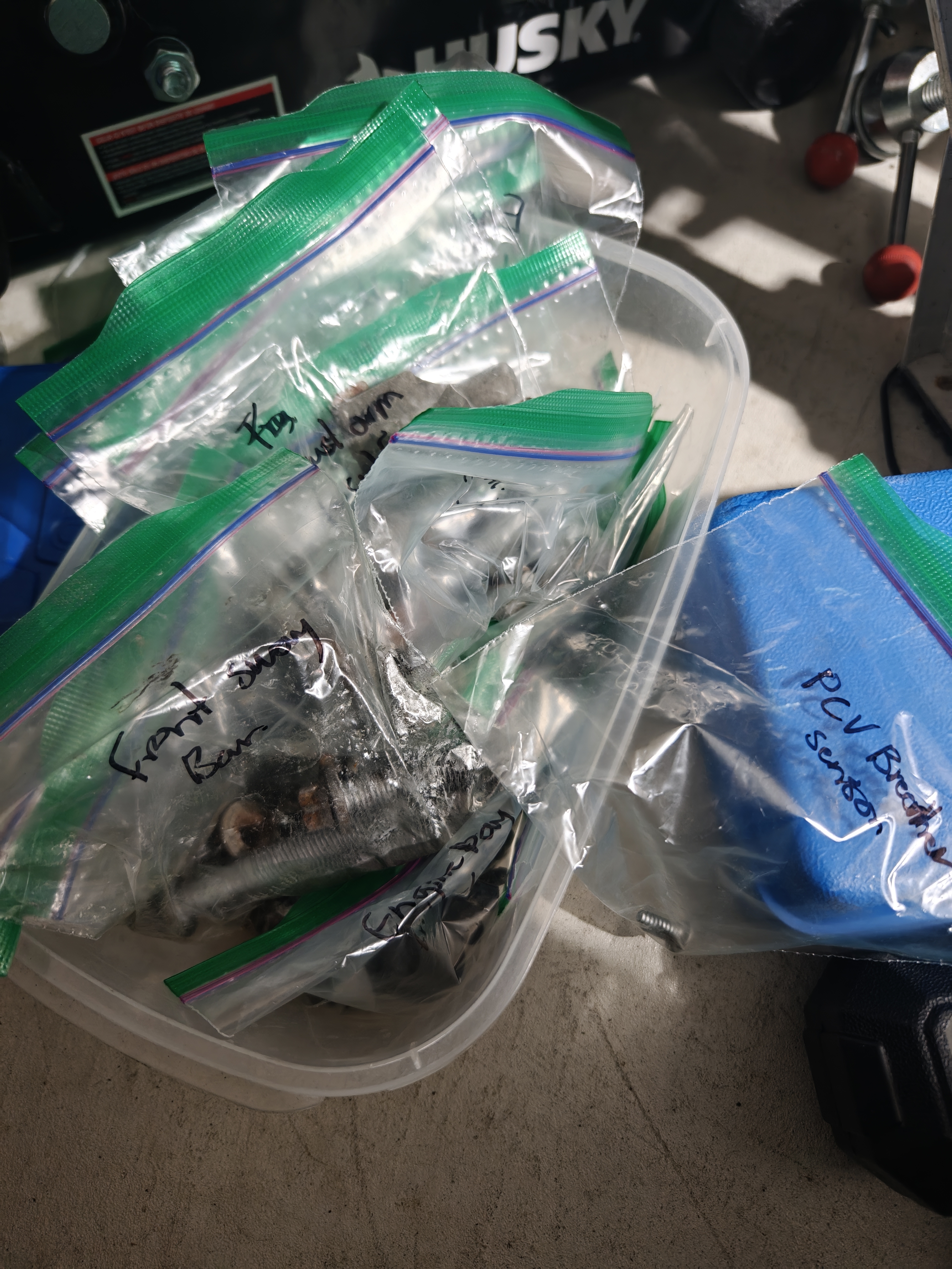 Image: Fasteners organized in labeled Ziploc bags
My plan was to take apart the engine first to inspect the oil pan and connecting rod bearings, which have the smallest clearance in the engine, to check for damage. That would let me assess whether the engine was worth saving. Then I could decide whether to repair or replace parts, or explore whatever other options I could think of.
Chapter 5
This section covers the step-by-step disassembly process. Click each step to expand the details.
I started in the summer of 2025. The first step was removing the front subframe to open the oil pan and get a good view of the engine internals. One of the most challenging parts was removing the front steering rack and pinion. To remove that, I first had to disassemble the front suspension.
I removed the front wheels and supported the vehicle from the front jack points on the chassis. Then I took off the bolts that connect the front control arms and thrust arms to the subframe. Actually, first I had to remove all of the plastic shielding as well. My god, these cars have a ton of shielding held on by dozens of clips and little self-tapping 8mm hex-with-washer fasteners. I spent a lot of time wiggling out the steering rack. The power steering lines are not friendly on this car because of the tight packaging of xDrive. In fact, originally all FXX-series cars were supposed to have electric power steering, but the xDrive AWD version did not have the space because the front of the car needed to allocate room for the front drive axles and front differential. So the older hydraulic power steering system was packaged with these cars instead.
After removing the tie rods from the front wheel hub knuckles, disconnecting the power steering lines (draining and catching the fluid, it's expensive CHF-11S after all), and disconnecting the electrical connectors, I finally got the first step done.
The next step was removing all the remaining connections holding the subframe to the car. I decided this would be the best course of action because it would give me the most room to work with. I wanted as much space as possible because I was working in a cramped garage on my back under the car, rather than with a nice spacious shop lift or hoist. It didn't help much that during the time the car was in storage, a rodent had moved into the engine bay and filled the subframe with dirt and feces, which I slowly scrubbed out as I worked.
I disconnected the steering shaft and locked the wheel straight in the driver seat using the seatbelt. This is to prevent accidentally turning the wheel too far and destroying the steering wheel's clockspring mechanism. I also marked the position where the shaft was attached so I could reinstall it in the same spot. After this was complete, there were still a few connections and wires attached to parts of the subframe that I knew would have to be removed. One of the trickier ones was the transmission cooler lines that are bolted down with a metal bracket. There's really no space and no good angle to tackle those fasteners. I had to literally twist myself into the passenger wheel well to reach them, and painstakingly remove the bolts one-eighth of a turn at a time. It took over 30 minutes to remove each of the three bolts holding it on!
Now onto the engine mounts. The N55 engine has two mounts that hold the engine in place and support its full weight on the car subframe. Additionally, the back of the engine is supported by its connection to the transmission bellhousing. Note that because of this design, when the subframe is out, the entire engine is just hanging by the transmission. Normally this would permanently damage the engine and transmission if it were not supported, but I had added an engine support bar. This support bar sits on top of the engine bay and is made of thick steel square tubing. The tool itself is nearly 50 lbs, and it needs to contact the strong inner part of the car frame chassis. So I removed the top plastic shielding on the engine bay and assembled and set up the support bar via a chain and hook, into a tow hook that threads into the top of the engine block. Now I would be able to remove the engine mount bolts and slowly lift the engine off the subframe to protect it from any damage when I dropped the subframe out of the car. After all the connections I could find were removed and all brackets and shielding taken off, I was finally ready to drop the subframe and gain access to the oil pan.
But it didn't budge. As it turned out, documentation for these cars is a bit limited online, and not many people have taken the effort to do the types of repair I was attempting. It turned out the subframe also bolts to the front crash structure to really tie the bumper and whole front of the car into a single strong part. I had to remove those bolts too, and wiggle around a bunch of tubing. The bolts were only accessible from behind the front brake cooling air ducts, which also had to be removed. Finally, I was able to slowly wiggle the subframe down onto a hydraulic floor jack and drop it out of the car.
Now I finally had access to the engine. But wait, there was still a little more work to do. These cars are AWD, and in an effort to reduce vertical height and achieve compact packaging, BMW designed them so the front driveshaft passes through the engine oil pan via a machined axle tunnel with supporting bearings and oil seals inside. This meant the axles and front differential had to come out before the oil pan could be removed. So I purchased a CV axle slide hammer tool to help with this job. I had actually tried for hours to remove the axle from the differential using pry bars and hammers, but even with the utmost strength I could muster, it would not budge. However, just a few whacks with the right tool did the job. This step also required a 17mm hex bit to remove the axle from the front wheel hub assembly.
Finally! I could open up the engine! Or not. One last thing to do: the front of the oil pan is integrated into a mounting bracket for the power steering pump. So, removing the front engine fan, loosening the engine belt tensioner, and then loosening the pump (which I let hang by some zip ties), followed by removing the power steering pump bracket, finally gave me access to the oil pan.
My next step was to assess the internals of the engine. I used an extension and an E10 socket to remove all the oil pan bolts, then dropped the oil pan. Clearly the oil had not been changed often enough in this car's lifetime. The oil pan was filled with metal debris and dark carbon deposits. Inside the engine, there is a suction plate and oil pump, which also needed removing. Then finally I was free to inspect the connecting rod bearings. I broke them loose with a breaker bar, then labeled and inspected each one for damage. I also removed the ignition coils and spark plugs and plugged the holes with cloth to make the engine easy to turn over. This let the pistons slide easily in their bores for inspection and bearing replacement.
Now a key thing to understand is that the crankshaft of this engine is made of induction-hardened cast steel with a surface hardness of approximately 50 Rockwell (HRC). Consequently, the debris that infiltrated the engine consisted primarily of particles in the 0.01 to 0.2 mm range, made of a softer aluminum alloy. After Plastigauging the crank journals, I noticed their specs did not differ much from new, at around 0.035 mm clearance. The surface properties of the crank journals had changed, however. I did consider polishing them with Scotch-Brite or DIY methods, but I refrained because of the potential to push the bearing out of round. The out-of-round tolerance of these parts is as tight as the oil clearance, which is fractions of a millimeter. This is much too small to accurately determine by even the most skilled hands, so instead I thoroughly inspected the surface finish by hand.
I noticed that even with moderate pressure, my fingernails were unable to catch any ridges on the crank journal. This means the scarring from debris is less than around 20 to 30 microns. From the evidence, I determined the damage to be mainly cosmetic due to a phenomenon known as "metallic smearing," where softer metal becomes embedded into the surface of harder metal, like how a crayon draws on paper. It's tiny microscopic fibers catching tiny microscopic flakes of material that turn the surface a visibly different color.
Additionally, after studying wear mechanisms and wear resistance in surface hardness, I determined that the main damage would be limited.
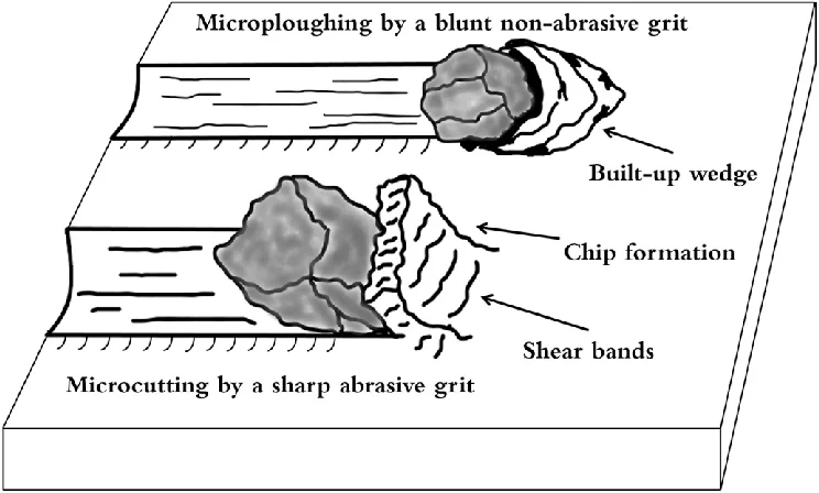 Image: Destroyed turbocharger compressor
After thorough metallurgical analysis, the engine was deemed worth saving. The repair would proceed.
Chapter 6
With the decision made to save the engine, it was time to order parts and begin reassembly. Click each step to expand.
I then ordered the parts I needed from FCP Euro and then got to work:
After the parts arrived, I began by reassembling the bottom end of the engine first because I noticed my flexplate had started to rust from air exposure. I wanted to seal up the engine as soon as possible. Using Permatex assembly lube and a plastic wedge, I rolled new bearings into place for each piston. Then, using an angle gauge, I torqued each piston's connecting rod bolts to the required specifications.
Honestly, this was extremely difficult to do while lying upside down with little leverage and minimal friction on the cardboard underneath. I kept sliding around because the force required to tighten these grade 12.9 bolts is incredible. I was able to complete three cylinders before I didn't have enough energy to continue and had to wait another day.
During the process, I also thoroughly inspected the cylinder bores for any signs of damage. Honestly, the cylinders looked amazing. They were extremely smooth and shiny with a nice light yellow varnish. These engines use a plasma-sprayed liner with microscopic pores to hold oil during operation. It is imperative that they look spotless, and mine did. This confirmed the aluminum particles had not made their way past the cylinder walls into the engine. The debris must have entered through the intake port, where a tiny hole opens from each intake runner to the crankcase to route oil fumes into the combustion chamber. Under boost, this airflow reverses and forces extra air into the crankcase. This was the path the debris took!
It is important to note that you must be extremely careful not to push the piston too high, or the piston rings will unseat. If that happens, you will be forced to rebuild the engine entirely.
After carefully reassembling the engine's bottom end connecting rods, I replaced the engine oil pump and suction plate with new bolts (all internal bolts are TTY and need to be replaced). I installed new oil pan bolts and a new oil pan gasket to seal up the engine. I also cleaned out the oil pan first with heavy-duty industrial grease remover until it was spotless inside and out!
Chapter 7
With the bottom end sealed, the next major task was rebuilding the destroyed turbocharger. Click each step to expand.
Once I decided to repair the engine, I knew I would also need to replace the turbocharger. A complete replacement turbocharger is quite expensive, so I opted to rebuild the turbine core by hand instead. This was a significantly cheaper option. You can almost always trade repair costs for additional labor, and this is what I did here since it was my own labor.
I decided to go with a Chinese-made turbine core for several reasons. My logic was this: China has a rather advanced industrialized society, and much of their population prefers German luxury cars because they are seen as a status symbol of wealth. Additionally, there must be a substantial domestic repair market for these cars because authentic German parts are rather expensive. So I searched for their domestically produced clones.
Upon finding one, I investigated the company at https://powertecturbo.com/. Although their claimed VSR stability is quite impressive (0.5 mm/s), practical real-world tolerances suggest that the absolute best available units are around 1 to 2 mm/s, and aftermarket options can range from 4 to 6 mm/s, which is still acceptable. I was still skeptical until I stumbled upon their https://powertecturbo.com/about-us/ page and saw that they actually have German-made balancing machines and 5-axis CNC machines, specifically ZEISS dimensional measurement and Schenck auto-balancing equipment. Billet aluminum is not hard to come by as it is reasonably priced, so I took an educated risk and tried one of their products.
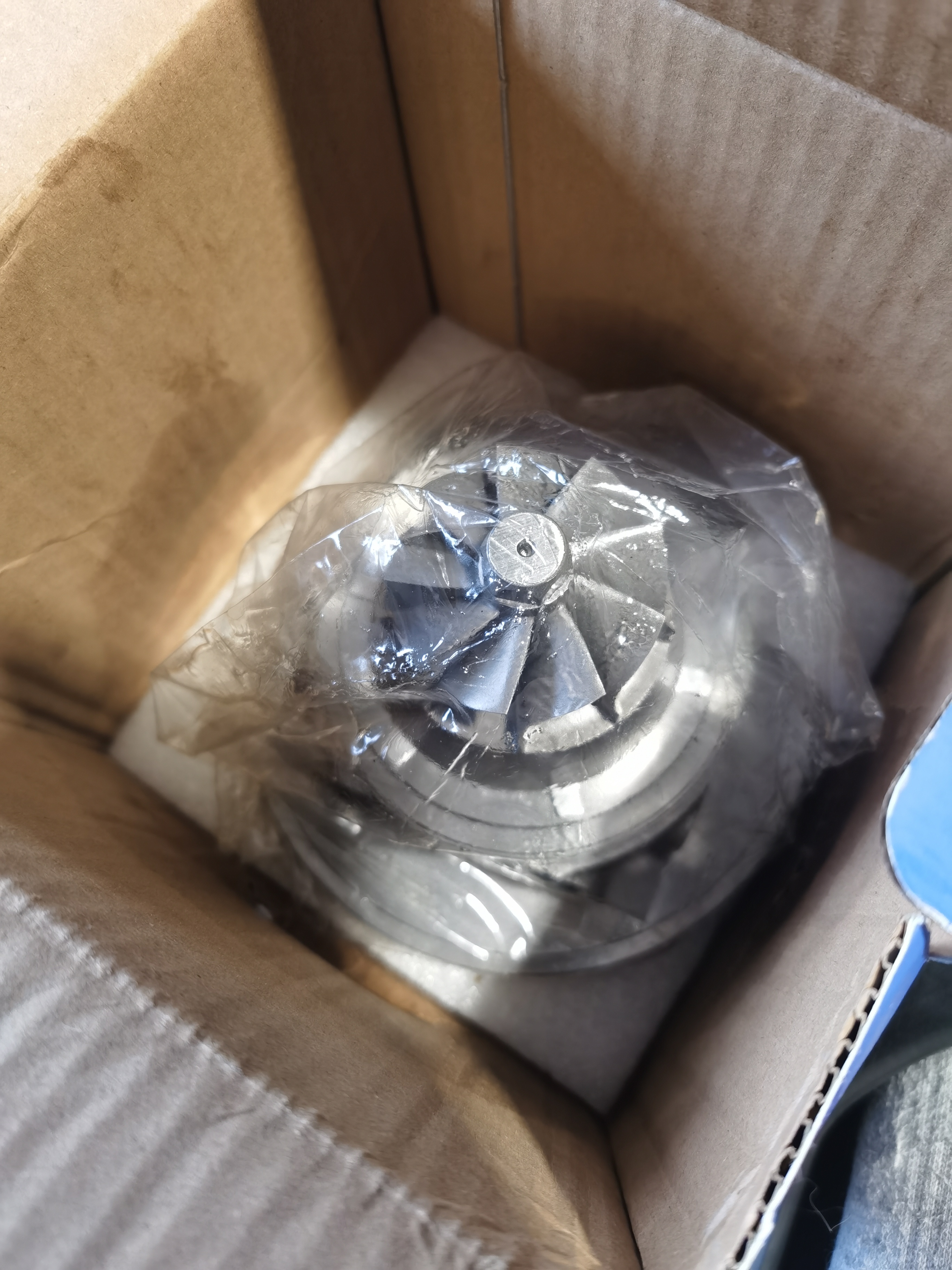 Image: New turbo core from powertec
For the turbine rebuild, removing the turbo from the car was quite a challenge. The Hot-V design of the N55 means the turbo assembly sits underneath the engine at a 40-degree angle, sort of hanging down. The turbo is surrounded by a compact packaging of coolant tubes, electrical connectors, and airflow passages. I disassembled and drained the engine coolant from the water jacket off the block itself, then removed all the tubing and electrical connections, bagging and labeling each one. Next, I broke apart the turbine housing and removed the turbo core, which was absolutely destroyed. Using a clever trick with paper to make a positioning template, I replaced the old core with a new one. I washed and cleaned all debris and oil off the housing, the compressor side, and the exhaust manifold leading to the turbine side. I fitted new graphite gaskets and new copper stud bolts, then bolted it back onto the engine.
This was a rather difficult endeavor as well, because the entire turbine assembly weighs around 50 lbs and sits in an extremely awkward position. I managed this by "ratcheting" up the assembly using heavy-duty zip ties wrapped around my turbo and the engine support bar until I could get two bolts in place. Then I seated the turbo to the engine block and tightened everything according to the specific BMW-supplied torque sequence for the 15 copper bolts. Many extensions were needed, and this was tough! There is very little space to work with in this engine haha.
Chapter 8
With the major engine work complete, it was time to put everything back together — and make a bold modification. Click each step to expand.
Now after the major repairs had been completed, I still had to replace all of the supporting structures, front suspension, fluids, and shielding. I took the time to do this carefully, as I had already put three months of physical work into the project. Replacing the front subframe was not too hard. The main trick is to connect the engine mounts first, because when they are new, the mounts are actually too large to fit between the engine and subframe. Additionally, the subframe of this F-series chassis is pinned with dowels, so alignment is very easy and almost impossible to screw up. I took my time and slowly raised it with a floor jack into position before tightening down the subframe bolts. According to ISTA, these bolts need to be replaced, so I replaced four of the six bolts. I didn't bother replacing the last two rear subframe bolts, and instead torqued them down to a calculated yield range that I figured would hold about 80% of their max rated clamping force, around 200 Nm. After all this, I could finally take off the engine support bar. The engine was once again supporting its own weight on the car's frame.
The next step was replacing the rack and pinion into the subframe, which was surprisingly easier than removing it. Just a bit of wiggling and it went right into place. Connecting the steering rack lines was a little more tricky because once the rack is in place, there is little room to reach the bolts for the lines. But with a little bit of contortion, I was able to tighten them down. It's not too difficult because the torque specs for these small bolts and screws are pretty low, so hand tight will do for most of them. After all, it is the O-ring which forms the mechanical seal in these systems, not the clamping pressure of the bolt. It's always important to understand the fundamentals of the system you are working on to understand how and why you can and can't do things the way you want!
After that, I put the front suspension back together, threading the large M14x110mm bolts into the subframe and control arms on each side. I hooked up the tie rods to the wheel knuckles and connected everything back. It was at this point that I decided I wanted to permanently convert my vehicle to RWD. There are plenty of forum posts about people attempting this specific thing and plenty more debates surrounding the topic. I would like to formally bring my experience and reasoning into the conversation.
For my RWD conversion, I simply removed the output shaft of the ATC35L transfer case. It should be noted that the rear differential will now take on 100% of the driveline load, and this is actually okay because the differential part number for the RWD and AWD cars is the same. I then disassembled the front axles and took their outer Rzeppa joint couplings and bolted those into the front wheel hubs. The reason I did this is because the front wheel bearings are actually tapered bearings, and the bearing preload is set by a bolt that connects from the brake rotor side to the CV axle behind it. It is essential to keep this part, as it actually holds the bearing assembly together. Without it, the wheel will fall off under driving load! Do not do this modification if you don't know what you are doing!
The front wheel bearings require the CV axle coupling to maintain bearing preload. Without it, the wheel will fall off under driving load. Do not attempt this modification without full understanding of the system.
Additionally, there have been many rumors online about x-delete (which is the software method) of turning these cars into RWD mode. The creators of x-delete claim that no other solution than their software is safe (of course they would claim that!) and that physically removing the transfer case output shaft will cause the transfer case to overheat because there is an oil pump on the front output shaft. Based on my research and the ATC35L design diagrams, I believe that the ATC35L transfer case does not have a dedicated oil pump. Instead, the clutch packs are lubricated as a result of the internal gear interference as seen in this diagram.
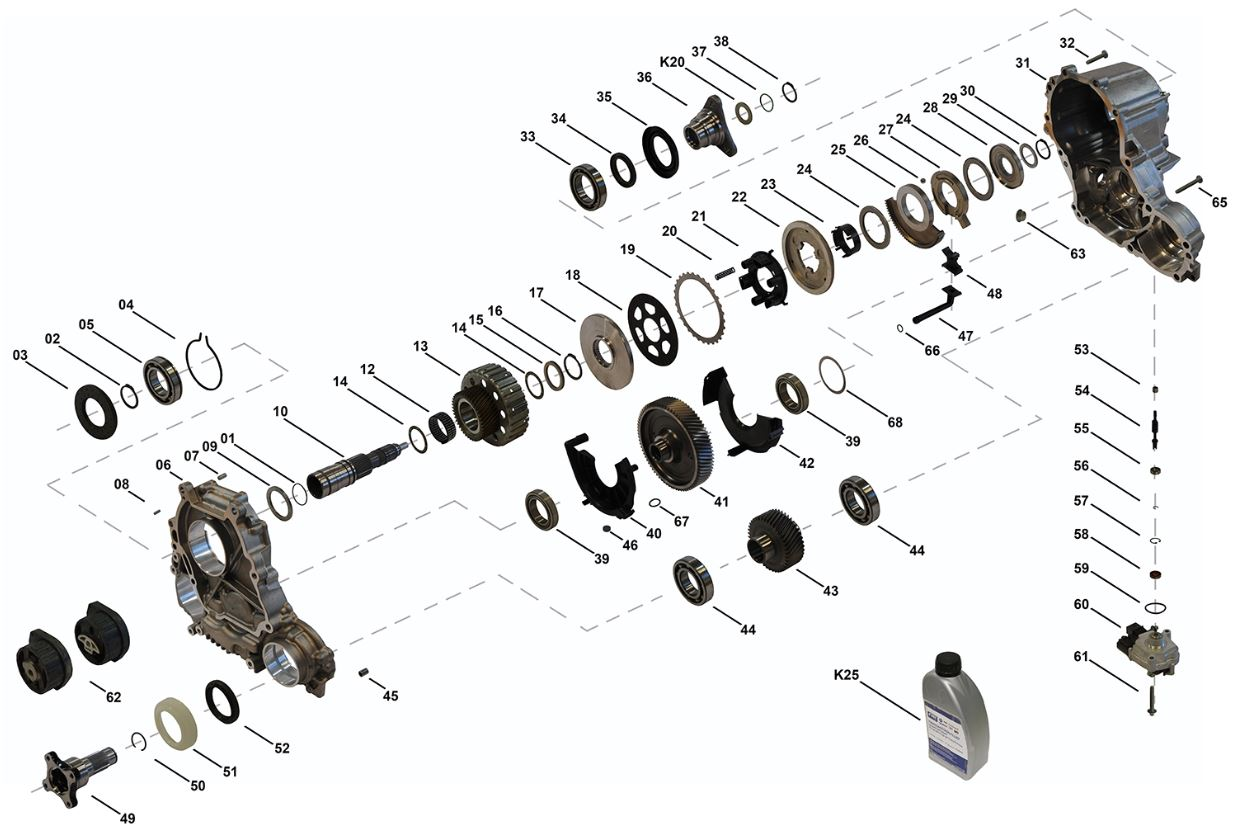 Image: ATC35L transfer case internal diagram
The key design principle behind this transfer case is that it is non-chain driven, which is odd. Traditionally, transfer cases do use chain drives. However, notice that this transfer case has two meshing gears (41, 43) and an oil inlet (40) between the gears where both sets of teeth mesh. This creates a "pumping" action by increasing the pressure of the oil in that region of the inlet. Then by passive pressure, the inlet allows oil to flow upwards to the clutch packs.
Also, note that this TC requires a very specific oil, a type of PAO called Shell TF-0870 or an equivalent SAE 75W GL-4 oil without sulfur additives. You cannot use differential oil, as it will eat away the clutches and plastics and rubbers inside. The reason for this design choice is the same reason why they are able to get away without a dedicated oil pump: the PAO resists viscosity change at temperatures, allowing for oil flow to be exactly in design specifications. Other fluids will not fulfill this property, which is why this very specific, very expensive fluid is required for the ATC35L.
Because of this, I made sure to top up my TC with some fresh fluid just to be sure it was getting all it needs to operate. Even though I no longer use the clutch packs for front wheel output, I topped the fluid up anyway to ensure reliable operation of the internal ball bearings and smooth power transfer. I used a GL-4 equivalent from Red Line Racing.
Chapter 9
After all of this had been completed, I refilled the engine coolant with OEM brand premix. This is another critical step that does not have any reliable substitutes. BMW uses a very specific silicated organic additive technology formulated specifically for aluminum engine blocks and components. I ran the bleed procedure according to ISTA repair documentation until the coolant reservoir was filled to maximum. I also filled the engine with 5W-40 SuperTech oil. I went with a budget BMW-LL01 certified oil because I wanted to wash out any remaining contaminants from the engine and internal oil passages, since I cannot manually reach everywhere that debris might hide.
I connected the car battery and then let the engine turn over with the fuel injector harness disconnected. Remember, the spark plugs and coils were also out at this point, so the engine was just freely spinning. This is important because the N55 suffers from dry starts that can easily destroy the engine. This is a well-documented phenomenon whenever the oiling circuit is opened. I primed the engine oiling system by turning it over until I saw oil in the oil filter at the top of the engine. Then I primed it again, and finally one more time to make sure oil had reached my turbocharger feed as well. Finally, I was ready to start up the engine!
After months of work, the engine fired up and ran smoothly. A moment of incredible relief and pride.
You can see the first start here:
Chapter 10
After running for a few minutes, I flushed the oil out with fresh oil and took it for a drive. It drove wonderfully smooth! Now, at the time of writing this blog in the spring of 2026, 20,000 km later, it is still driving excellently. I have changed the oil two more times since then at increasing intervals, and each time the oil has come out with less debris. This is why I am confident all the existing debris has been flushed out. The turbine is building boost nicely and it pulls hard, so everything is working as expected. There have been no error codes since the first startup!
 Image: car
 Image: car
Chapter 11
Chapter 12
I am extremely happy and proud of my work, especially considering I had zero mechanical background and never even touched a car until I was well into my twenties. Little did I know that just four years later I would be rebuilding the engine of a car in my parents' garage. It just goes to show that whenever there is a will, there is always a way. This project proved to me that with research, patience, and the right resources, I can tackle complex mechanical problems I once thought were beyond me!
I ended up doing a wheel alignment myself later in the year as well. I eyeballed the front alignment because the rear thrust angle was already verified by a professional alignment the prior year. This is not a general recommendation; proper alignment requires precision equipment.
If you would like to see my other projects, which include an ENET diagnostic and logging scanner for engine telemetry, check them out here: [link]. Otherwise, have a nice day!
Shoutout to my apprentice who I could not have completed this project without.
 Image: Fasteners organized in labeled Ziploc bags
References
Forums, documentation, and parts suppliers used throughout this project.